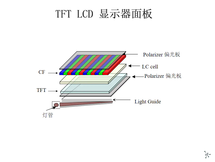
Build an interactive arcade bedside table with touch screen and animated arcade numbers where you can record the sound of your alarm clock. This is an update to the previous project and now includes a 3D print case and four separate programs to choose from. Arcade Clock - DK Mario, Space Intruder and Pacman Animation 2Pacman Clock - Interactive animated Pacman game with clock function. DK Clock - Interactive animated DK game with clock function. Tumble Ghost - Animated Pacman ghost game based on flying birds offers a great gift for anyone who likes to relive the nostalgia of 80 arcade game characters ** if you like this note, please in the \"clock race\", press the button at the bottom of the page ** Thank you very much! ! Only when I print the clock box on Creality Ender 3 is the optional auto Backlight dimming component required. All 3D print files and shell instructions can be found on ThingiverseThe. The entire circuit contains real-time clocks, Arduino Mega, sound modules, touch screens, and screen screens. 1. The live clock installs the live clock on the back of the Arduino Mega as shown in the figure. I used hot glue guns and packaging foam to make sure they don\'t touch and have some buff to absorb the movement. In my example, I soldered two RTC legs directly to the Arduino and connected 5v and GND to the Arduino using a connecting cable. 2. These recording modules are very cool and easy to use. As mentioned above, the modules and speakers are placed on the back of the Arduino using foam and hot glue to ensure they are free from touch. The sound module is triggered by the D8 on the Arduino, so this and the power supply need to be connected according to the supplied circuit diagram. 3. Automatic backlight dimmer (Optional) If you\'re going to use it as a bedside table, then you might want to automatically dim the backlight at night so it doesn\'t affect your sleep. ( If not then you can skip this step! ) Unfortunately, the backlight on the TFT screen is hardwired into +3. 3 v, cannot be adjusted using Arduino. This means that we have to disconnect it and reconnect to the PWM pin on the Arduino to control the backlight brightness. I want to do this with minimal pin or track damage on the assembly, so take the following approach. Follow the following steps carefully (a) To achieve this, a resistance that depends on light (LDR) Located on the back of the device for detecting light. Drill Two 3mm holes in the shell and pass the LDR leg through these holes. Use hot glue inside the cabinet to fix the legs in place. According to the circuit diagram, weld two wires inside the shell and connect them. According to the circuit diagram, add a 270 ohm resistor to the A7 of the Arduino. (b) Remove the TFT display and place it on a solid surface. Identification Pin 19 (LED_A) Carefully remove a few millimeters of plastic from the bottom of the pin. Bend the pin flat and away from the connector, according to the picture above. Check if the TFT case can be plugged in tightly, and if the curved pin does not hinder the plug or socket. (c) Weld the 47 Ohm register to the bend on the pin and connect the wire on the resistor to the D9 on the Arduino Mega. The Arduino D9 pin can absorb up to 40 mA, so the resistor limits it to less than that. Attach a 3. 3v Zener diode to the same pin (LED_A) And connect it to the Earth according to the chart. The purpose of this is to protect the backlight from over-voltage because it will adjust the voltage to 3. 3v. 4. TFT screen and Arduino Shield push 3 carefully. 2\' TFT touch screen connector in TFT Arduino shield. Then carefully connect to the top of the Arduino according to the picture provided. The RTC has a battery, so it will keep the right time even if it is powered off. The alarm time is stored in the Eeprom on the Arduino, which means that it will be retained if power is cut off. Before compiling and running, the project will need to load the following files and libraries. The code is unique and built around the features I borrowed from libraries, hardware, some custom graphics, and other projects. Please note: the code that developed this project uses IDE v1. 06 and the dates of some libraries needed. This means that some people have a problem with the new IDE Version 1. 6 or more when loading code. So for simplicity, I would suggest that people use IDE v1. 06, and include the correct version library file in the zip file at the bottom of step 4 of instructable. 1. Arduino ide I have been using an earlier version of the Arduino IDE, so for the sake of simplicity I suggest you download Arduino IDE Version 1. 06 before installing the code on your desktop machine. You can get his version from here. 2. These libraries need to be downloaded and added to the IDE ( Integrated development environment) It runs on your computer for writing computer code and uploading it to a physical board. UTFT credit. h and URtouch. H to linky- Dink electronics, I have included these zip files when the source site is closed. 4. The change of TFT screen and the blur of the manufacturer lead to these precautions. (a)Sainsmart - If you have already purchased 3. Put a 2\' TFT screen of the Sainsmart brand on the back of the TFT device and you will find that they have to modify the library to solve the display problem. If you have purchased the Sainsmart TFT display, then there is a fix under the file \"initlcd. H \"and from mlcd _ write _ com _ data (0x01,0x2B3F); Told_write_com_data (0x01,0x3B3F); You will need to restart the IDE and then reload the code to Arduino. (b. ) TFT controller chipset People who bought 3. 2 \"TFT screens may find that they can also have\" SSD1289 \"or\" ILI9341 \"in one of two different chipsets\" The good news is it\'s easy to fix. If a blank screen appears after loading the code, then it may be because it is the ILI9341 controller. To fix, you need to make the following changes to the code. Edit the code and modify the following line of code myGLCD ( SSD1289, 38,39, 40,41);
Thank you for your message!
We are LCD Mall, committed to providing customers with high-quality services and products. Our salesperson will contact you as soon as possible.
If you have urgent questions, please feel free to contact us directly through WhatsApp or email: WhatsApp: 86-13713689582/ info@AllTouchDisplay.com .
Hello, please leave your name and email here before chat online so that we won't miss your message and contact you smoothly.