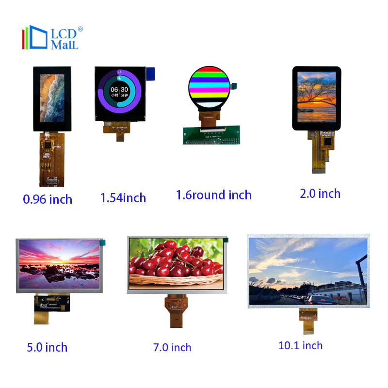
LM-SPI-Module
beginner arduino - using a 1.8 inch tft display
by:LCD Mall
2020-07-20
This is the Getting Started Guide for you to use 1.
TFT display with Arduino. I like the 1.
It is small in size and low in cost.
I bought mine for about $10 on ebay.
It doesn\'t come with instructions, but I was able to get it to work with some research and patching.
You need the following: Arduino Duo R3 ($10-25)1.
8in TFT display ($10-20)
Jumper Cable computer with Arduino IDE1k ohm resistor (5)
Adafruit offers 1 for around $20.
8 in the presentation, their products have a good tutorial on their website.
This is not a tutorial for their product, it will be redundant.
First, we will look at the pins of the display boards and what they do, then look at the wiring schematic, and finally, you will load the code to test the display.
The first photo here shows the back of the display board.
Two sides of the pin-
One side of the red circle is the one we are going to work.
It has 8 pins and you can see what each pin corresponds to in the second photo.
The other side with 16 pins is used to use the SD card, which will be stated in the instructions later.
Brief summary of pins (
Adapted from a thorough summary of Adafruits):RST -
This is the TFT reset pin.
Connect ground reset TFT!
It\'s better to have this pin controlled by the library so the display can be reset cleanly, but you can also connect it to the Arduino reset pin, which works in most cases. CS -
This is the tft spi chip selection pinD/C-
This is tft spi data or command selector pinDIN-
This is the SPI Master output in the pin from the device (MOSI)
, Used to send data from a micro controller to an SD card and/or TFTSCLK-
This is the SPI clock input pinVcc-
This is the Power Pin, connected to 5VDC-
It has reverse polarity protection, but try wiring it right! BL -
This is the input of backlight control.
Connect to 5VDC to turn on the backlight. GND -
This is power and signal ground, now that we know what we\'re dealing with, it\'s time to start wiring!
This is a step I hope to be able to find more easily when starting to use this board.
When I received the screen and realized that I didn\'t know how to connect it, I turned to the Adafruit guide for their products.
At first it looks like the pin layout is different, but on top of that, the two monitors are interchanged and are able to run the Adafruit graphics library (
More code about the next step).
However, when I connect my motherboard as per the Adafruit guide, my monitor is a bit working.
It does show text and graphics, but there is a lot of noise in the image and the image becomes clearer on the screen.
It also emits bright light along the top of the screen, interrupting the image quality.
I think this is because I run the screen under 5v and it needs lower power. I tried 3.
3 V, the display gets worse.
I regret my purchase on eBay after about 10 minutes and hope I have gone to Adafruit board, I decided to Google my question and found this post about similar1.
8in SPI 128x160 TFT module Arduino)
In short, 1k ohm resistance is required between 5 connections.
You can see the position of the resistor in the Fritzing figure.
The second picture is a table connecting the pins on the display to the Arduino.
I listed them below and pointed out if a resistor is needed for the connection. RST -Arduino Pin 7 -1k ResistorCS -Arduino Pin 9 -1k ResistorDC -Arduino Pin 8 -
1k resistor-
Arduino pin 11-
1k resistor-
Arduino pin 13-
1k resistor vcc-5VBL -5VGND -
GNDYou need to install two libraries in order to operate the display: download each library and decompress the folder.
Rename them to \"adafruit_st7735\" and \"adafruit_gfx\" and place each folder in the Arduino Libraries folder.
I have attached a screenshot of the library in the correct folder.
After installation, you can operate the screen!
There is a file named graphicstest in the Adafruit ST7735 Library.
You can upload to Arduino\'s ino, which will run through many features that draw objects to the screen.
However, some changes need to be made to this file in order for the pins to fit into the layout.
Alternatively, you can copy/paste the following code into the Arduino IDE and upload it.
This is a modified version of graphictest for Adafruit.
Ino, the main difference is the distribution of pins.
I also played with the code a little to see what kind of features are available.
Let me know if you have any code problems.
This is good for me.
This is all about it.
My video for this step shows what the expected display should look like if you run the above code.
Enjoy your new display!
Custom message